Altimexor Metal
Welding dissimilar steels demands more than a clean joint and a steady hand. Their different carbon levels, alloying elements, melting ranges, and thermal expansion rates can create hidden risks. A bead may look smooth while cracks develop beneath the surface. Distortion can also pull a carefully aligned frame out of shape.
This guide explains how to weld different types of steel safely, using practical preparation and controlled welding methods. It covers carbon steel, stainless steel, low-alloy steel, and common combinations between them. Material identification matters. Confirm the grade, thickness, condition, and service requirements before striking an arc. Guesswork is dangerous.
Use a qualified welding procedure when the joint carries structural, pressure, or safety-related loads. Select filler metal for compatibility, strength, corrosion resistance, and dilution control. Preheat only when the material and procedure require it. Monitor interpass temperature with a temperature stick or infrared thermometer. Keep stainless surfaces free from carbon-steel contamination. Small particles from a used grinding wheel can later become rust spots.
Protective clothing, a suitable helmet, gloves, ventilation, and fire controls remain essential. Welding fumes are not harmless smoke. Inspect the completed joint for undercut, porosity, cracking, and excessive distortion. Non-destructive testing may be necessary for critical work.
There is no universal setting.
Even experienced welders revise their plan after seeing arc behavior, heat movement, or unexpected contamination. Safe results come from verified materials, documented procedures, controlled heat, and honest inspection. This article offers sound guidance, but uncertain joints should be reviewed by a certified welding professional before service.
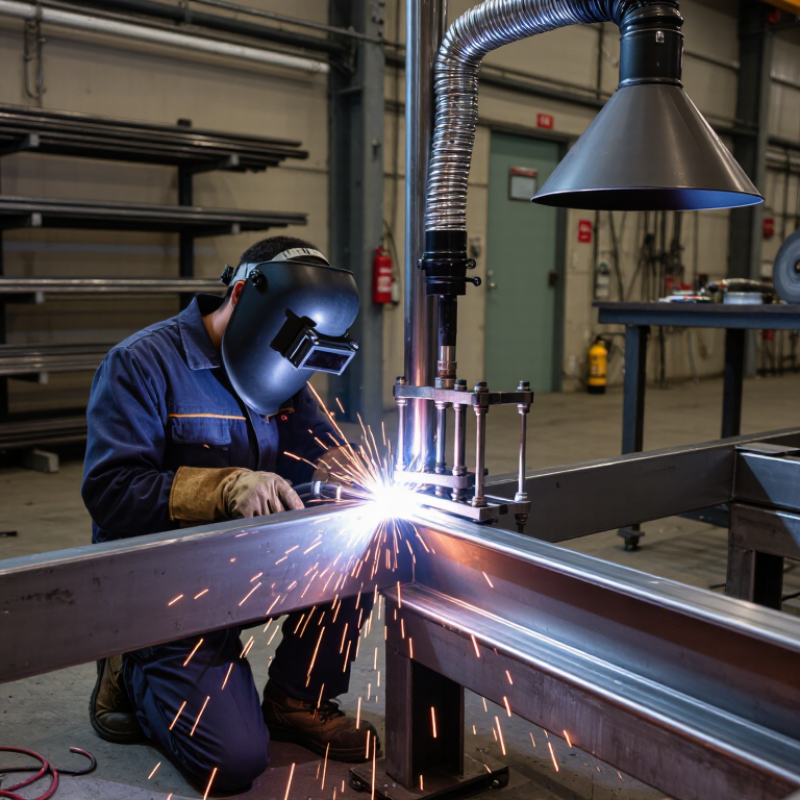
How to Weld Different Types of Steel Safely?
Identifying Steel Grades and Their Weldability
Steel may look identical on a workbench, yet its welding behavior can differ sharply. I have learned not to trust color, surface texture, or a quick visual match. Check heat numbers, stamped markings, drawings, and material certificates. Portable positive material identification can confirm alloy content when records are missing. A spark test may offer a clue, but it should not decide the welding procedure.
Plain low-carbon steel usually welds easily with suitable filler metal and clean joint preparation. Medium-carbon and high-strength steels need more control. Their carbon equivalent can indicate cracking risk and preheating requirements. Keep electrodes and joint surfaces dry. Control interpass temperature, heat input, and cooling speed. Stainless steel demands separate brushes and tools, because carbon-steel contamination can cause rust. Coated steel requires careful coating removal, ventilation, and protection from harmful fumes. Never weld an unknown grade casually.
Tips: Record the steel grade before cutting. Compare the grade with a qualified welding procedure. Use low-hydrogen consumables when hydrogen cracking is possible. Measure preheat with a temperature crayon or approved thermometer. Let the joint cool gradually. I sometimes want to continue after seeing a clean bead, but appearance proves little. A sound weld also depends on hardness, penetration, and hidden defects. When two grades meet, select filler metal for the joint’s weaker or more crack-sensitive side, then verify the procedure with a competent welding professional.
When welding different steels, filler metal selection should begin with the joint’s weakest and most crack-sensitive side. A stronger filler is not always safer. Check the base metals, carbon equivalent, dilution, service temperature, and corrosion exposure before choosing consumables. For carbon steel joined to stainless steel, an austenitic filler may reduce cracking risks, but the exact grade still requires procedure qualification. Nickel-based fillers can help with severe thermal expansion differences, yet they may add cost and new inspection concerns.
Keep the welding method compatible with the joint geometry and heat sensitivity. GTAW can provide a controlled root, especially on thin sections or critical piping. GMAW may improve productivity on longer seams, while low-hydrogen SMAW remains useful outdoors when electrodes stay properly dry. Preheat should follow calculated carbon equivalent, thickness, restraint, and hydrogen control. Do not guess it from appearance. Measure the steel temperature near the joint.
Cleanliness matters more than many welders expect. Use dedicated stainless-steel brushes and avoid carbon contamination. Control interpass temperature to limit distortion and unwanted microstructures. I have seen a visually smooth weld fail because the transition zone was ignored. That detail deserves more attention. Review the qualified welding procedure, then inspect root fusion, hardness, cracks, and dimensional distortion. If the metals, thicknesses, or service conditions change, the old procedure may no longer be reliable. A practical trial weld can reveal problems before production begins.
Different steels demand different preparation. Carbon steel usually tolerates light surface cleaning, but stainless steel needs separate brushes and tools. Carbon contamination can damage corrosion resistance near the weld. Galvanized steel is more difficult. Remove the coating from the weld zone, then control zinc fumes with local exhaust and suitable respiratory protection. A clean-looking joint can still be unsafe.
Check the material certificate before setting heat, filler metal, or preheat. Low-alloy steel may require controlled preheat and interpass temperatures to reduce hydrogen cracking. AWS D1.1 recommends using qualified welding procedures for applicable structural steels, while ISO 9692-1 provides joint-preparation guidance. These documents matter because guessing is not a procedure. It is a common mistake.
Ventilation deserves equal attention. OSHA limits airborne hexavalent chromium to 5 micrograms per cubic meter over an eight-hour period. NIOSH recommends a much lower exposure limit of 0.2 micrograms per cubic meter as a ten-hour time-weighted average.
Stainless preparation can create this hazard, especially when grinding or welding in confined areas. Measure the workspace when possible. Do not trust airflow that merely feels comfortable.
Remove oil, paint, moisture, and mill scale, but avoid aggressive grinding that changes the joint geometry. I still find that rushed cleaning causes more rework than difficult welding. Safety preparation is not glamorous. It is exacting work.
Welding different steels begins with heat control, not just amperage. Carbon steel, low-alloy steel, and stainless steel respond differently to thermal cycling. NIST thermophysical data places steel’s thermal expansion near 11–13 µm/m·K. A 1-meter plate can therefore expand over 6 mm during a 500°C temperature rise. I reduce distortion by using short welds, balanced sequences, and carefully spaced tack welds. Excessive restraint can create another problem: cracking beside the weld.
Hydrogen requires stricter discipline. Moisture, oil, rust, and damp consumables can introduce diffusible hydrogen. ISO 2560 classifies low-hydrogen electrodes using levels such as H5, meaning no more than 5 ml of diffusible hydrogen per 100 g of deposited metal. I keep consumables dry, clean joint faces to bright metal, and apply preheat when thickness or hardenability demands it. Preheat also slows cooling, allowing hydrogen to escape before the steel becomes dangerously hard.
Interpass temperature matters too. Excessive heat can enlarge the heat-affected zone and reduce toughness, especially in stainless or high-strength steel. I record current, voltage, travel speed, and temperature instead of trusting appearance alone. The IIW hydrogen-control recommendations support this measured approach. Still, inspection after cooling is essential. Delayed cracks may appear hours later, and my first temperature estimate is not always correct. That is where procedure records, hardness checks, and qualified inspection provide better evidence than confidence.
After welding different steels, inspection should begin only after the joint cools safely. I check the weld profile, toe blending, crater areas, and visible surface cracks. Look closely. A clean bead can still hide serious problems.
I compare the finished weld with the approved welding procedure and drawing. The leg size, reinforcement, alignment, and distortion must match specified limits. I also inspect for undercut, overlap, porosity, arc strikes, and incomplete fusion at accessible edges. Do not guess. Calibrated gauges provide more reliable measurements than visual judgment alone.
Testing depends on the joint design, steel grades, thickness, and service conditions. Dye penetrant testing can reveal open surface flaws on suitable materials. Magnetic particle testing helps find surface and near-surface discontinuities in ferromagnetic steel. Ultrasonic testing can examine internal fusion and hidden flaws. Radiographic testing may provide useful evidence, but it requires controlled access and qualified personnel. Hardness checks can identify excessive heat effects, especially near the heat-affected zone. Material identification may also be necessary when steel grades were mixed or markings became unclear. Records should include inspector qualifications, equipment calibration, test locations, results, and repairs. In field work, I have learned that rushed documentation creates uncertainty later. A weld should not be accepted because it looks attractive. Acceptance requires traceable evidence, suitable criteria, and a second review when the result is borderline.
| How to Weld Different Types of Steel Safely? - Inspecting and Testing the Completed Weld | |||||||||
|---|---|---|---|---|---|---|---|---|---|
| Typical welding, inspection, and testing parameters for common steel combinations. Final requirements must be confirmed by the approved WPS, project specifications, material certificates, and applicable construction code. | |||||||||
| No. | Steel Combination | Typical Welding Process and Filler | Preheat Range | Maximum Interpass Temperature | Visual Inspection Focus | Recommended NDT | Hardness Check | Mechanical or Corrosion Test | Typical Acceptance Requirements |
| 1 | Carbon steel to carbon steel Examples: structural mild steel grades |
GMAW, FCAW, SMAW, or SAW Low-hydrogen or matching-strength consumable |
50–100°C Higher values may be required for thick or highly restrained joints. |
≤250°C unless the WPS specifies a lower limit | Check weld size, profile, undercut, overlap, arc strikes, crater filling, porosity, and surface cracks. | MT for surface-breaking flaws; UT or RT for volumetric examination where required. | Typical control range: ≤350 HV10, subject to the governing specification. | Tensile, bend, and macroexamination tests during procedure qualification. | No cracks, lack of fusion, unacceptable undercut, or relevant planar indications. Weld dimensions must meet the drawing and WPS. |
| 2 | Carbon steel to high-strength low-alloy steel Examples: structural HSLA grades |
Low-hydrogen SMAW, FCAW, or GMAW Use a filler compatible with the required strength and toughness. |
75–125°C, depending on thickness, carbon equivalent, and restraint | ≤250°C; use a lower limit when toughness or heat input restrictions apply. | Inspect for delayed hydrogen cracking, excessive reinforcement, undercut, and heat-affected-zone damage. | MT after cooling and, where applicable, after a delay period; UT or RT for internal discontinuities. | Check the weld and HAZ for excessive hardening; typical project limits may be approximately 350 HV10. | Tensile, bend, impact, and macro tests when required by the qualified procedure. | No visible cracks or unacceptable lack of fusion. Strength, toughness, and hardness must satisfy the approved qualification criteria. |
| 3 | Carbon steel to austenitic stainless steel Examples: carbon steel to 304L stainless steel |
GTAW or GMAW Common filler selection: 309L-type dissimilar-metal filler. |
Normally no preheat for the stainless side; keep the carbon-steel side dry and within WPS limits. | ≤150°C is commonly used to limit sensitization and distortion. | Check for oxidation, excessive dilution, crater cracks, arc strikes, undercut, and contamination from carbon-steel tools. | PT for the stainless weld surface; UT or RT when joint geometry and thickness permit. | Check for localized excessive hardness on the carbon-steel HAZ; avoid treating stainless hardness as the sole acceptance criterion. | Macroetch examination, bend testing, and ferrite or metallographic checks when specified. | No surface cracks or relevant lack of fusion. Stainless-side contamination, oxidation, and corrosion-sensitive defects must be controlled. |
| 4 | Carbon steel to austenitic stainless steel Examples: carbon steel to 316L stainless steel |
GTAW or GMAW Common filler selection: 309MoL-type dissimilar-metal filler where molybdenum compatibility is needed. |
Normally no preheat for the stainless side; moisture control remains essential. | ≤150°C, unless the approved WPS requires a lower value. | Inspect for heat tint, lack of fusion, crater defects, undercut, arc strikes, and embedded iron contamination. | PT of the completed stainless surface; UT or RT when technically suitable. | Measure the carbon-steel HAZ when hydrogen cracking is a concern; evaluate stainless weld hardness only against project-specific limits. | Macroexamination, bend tests, and corrosion-related testing when required by service conditions. | No cracks, unacceptable porosity, or lack of fusion. The final weld must maintain the specified corrosion and structural performance. |
| 5 | Carbon steel to chromium-molybdenum low-alloy steel Examples: carbon steel to 1.25Cr–0.5Mo steel |
Low-hydrogen SMAW or FCAW Use a matching or qualified compatible Cr-Mo filler. |
150–200°C, based on thickness, restraint, and carbon equivalent | ≤250°C unless the WPS specifies a lower maximum | Check for delayed cracking, arc strikes, insufficient fusion, excessive heat input, and weld profile. | MT after cooling; UT or RT for internal weld quality. Repeat inspection after any required delay. | Hardness testing of weld metal and both HAZs; limits are commonly code- and PWHT-dependent. | Procedure qualification may include tensile, bend, impact, hardness mapping, and macroexamination. | PWHT, when required, must meet the specified time-temperature cycle. No cracks or unacceptable planar indications are permitted. |
| 6 | High-carbon or hardened steel to carbon steel | Controlled-heat-input SMAW, FCAW, or GMAW Use a qualified low-hydrogen or compatible lower-strength filler where permitted. |
150–300°C, determined by carbon content, thickness, restraint, and cooling rate | Typically ≤250°C; excessive heat can reduce base-metal properties. | Pay special attention to delayed cracking, hard HAZ formation, undercut, crater defects, and distortion. | MT after cooling and after a suitable delay; UT or RT for volumetric examination as required. | Mandatory HAZ hardness mapping where hardening or hydrogen cracking is possible. | Hardness traverse, macroexamination, bend testing, and procedure-specific toughness testing. | No delayed cracks or unacceptable hard zones. Cooling, consumable storage, preheat, and post-weld treatment must follow the qualified procedure. |
| Inspection sequence: Confirm material identification and traceability, review welding records, perform visual inspection, allow the joint to cool as specified, conduct surface and volumetric NDT, complete hardness or mechanical testing when required, document indications, and repair only under an approved repair procedure. Use calibrated equipment and qualified inspectors for all tests. | |||||||||
Check stamped markings, heat numbers, drawings, and material certificates. Portable material identification can confirm alloy content when records are missing. Do not rely on color, texture, or sparks alone. Unknown steel needs professional review.
Plain low-carbon steel usually welds easily with suitable filler metal and clean joint preparation. Medium-carbon and high-strength steels need more control. Their carbon equivalent can indicate cracking risk and preheating needs. Appearance alone proves little.
Choose filler metal for the weaker or more crack-sensitive side. Consider carbon equivalent, dilution, service temperature, and corrosion exposure. A stronger filler is not always safer. Confirm the choice through a qualified procedure.
Gas tungsten welding can provide a controlled root on thin or critical sections. Gas metal welding may suit longer seams and higher productivity. Low-hydrogen stick welding can work outdoors when electrodes remain dry. Joint geometry still matters.
Preheat may be necessary for thicker steel, higher carbon content, strong restraint, or hydrogen risk. Measure temperature near the joint with an approved thermometer. Do not guess from the metal’s appearance. Cooling slowly can reduce cracking risk.
Use short welds, balanced sequences, and carefully spaced tack welds. Control heat input and interpass temperature. A one-meter plate may expand several millimeters during strong heating. Excessive restraint can create cracks beside the weld.
Keep electrodes, joint faces, and tools clean and dry. Remove oil, rust, moisture, and damp residue before welding. Low-hydrogen consumables may help when hydrogen cracking is possible. Delayed cracks can appear hours later.
Carbon-steel contamination can cause rust on stainless steel. Use dedicated stainless-steel brushes and clean tools. Control heat to limit distortion and unwanted microstructures. I once trusted a smooth bead too quickly; the transition zone still needed inspection.
Inspect root fusion, cracks, hardness, penetration, and dimensional distortion. Record current, voltage, travel speed, preheat, and interpass temperature. A practical trial weld can reveal hidden problems before production. Confidence is not evidence.
How to weld different types of steel safely begins with identifying each steel grade, its carbon content, alloying elements, thickness, and heat-treatment condition. These factors determine weldability and help prevent cracking, brittleness, or loss of strength. Choose a compatible filler metal and welding method according to the base metals and the service requirements of the finished joint. When joining dissimilar steels, consider differences in strength, expansion, and corrosion resistance, and use a transition strategy when necessary.
Before welding, clean the surfaces thoroughly, remove coatings and contaminants, and prepare the joint with suitable fit-up and alignment. Control preheating, interpass temperature, travel speed, and heat input to reduce distortion and manage hydrogen-related cracking risks. Allow the joint to cool under controlled conditions when appropriate. After welding, inspect the bead profile, fusion, penetration, and visible defects. Depending on the application, use non-destructive testing or mechanical tests to confirm weld integrity, dimensional accuracy, and compliance with the required safety standards.